| mini‑DIN Pin | Description | DB9 Pin | Description |
|---|---|---|---|
| 5 | TX from LPFK | 2 | PC RX |
| 6 | RX to LPFK | 3 | PC TX |
| 1 / 2 | GND | 5 | Signal GND |
| 3 / 8 | +5 V input | 8 | +5 V input |
| 4 / 7 | not connected | 7 | not connected |
Reviving an IBM LPFK
Loading...
TL;DR: I picked up an IBM Lighted Program Function Keyboard (LPFK), wired its 8-pin mini-DIN to a modern USB-to-RS-232 dongle, reverse-engineered the “reset + enable + LED bitmap” protocol, and wrote a tiny Node.js app that prints keycodes and lights any key. This post documents the whole journey so you can repeat it (or just enjoy the rabbit hole).
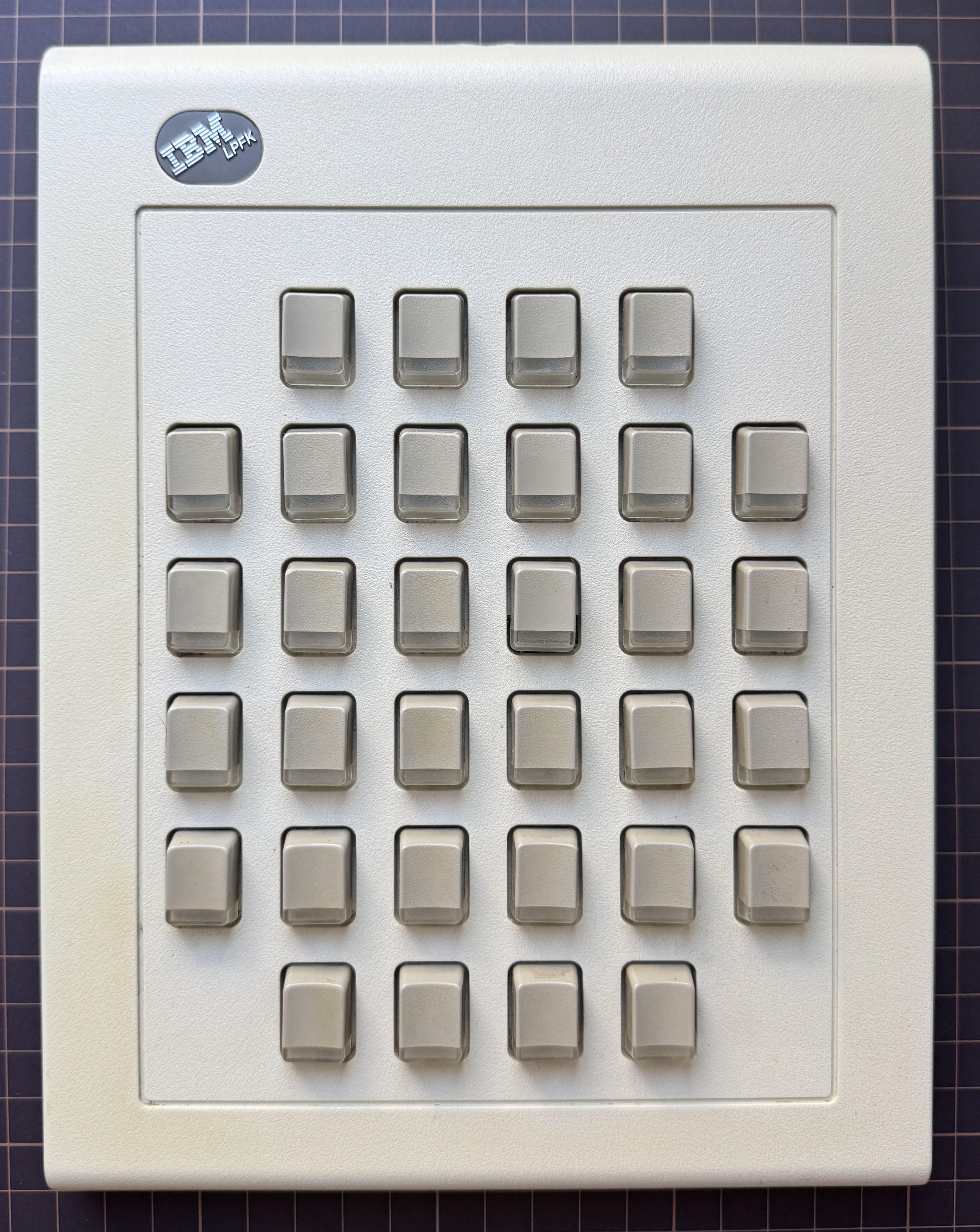
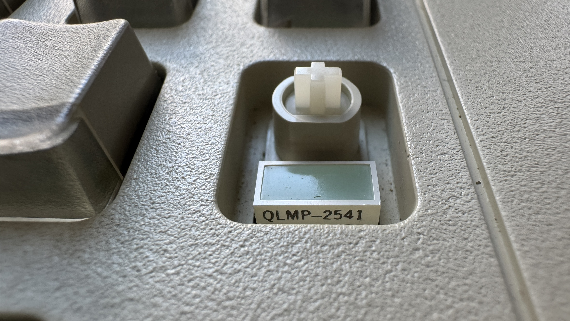
What is the IBM LPFK?

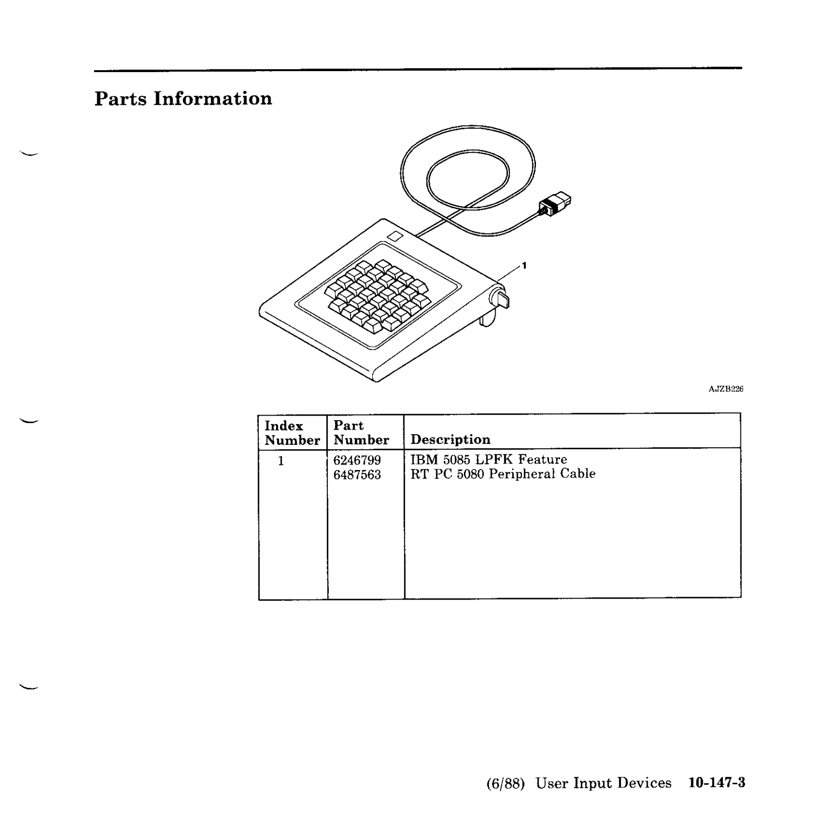
The IBM Lighted Program Function Keyboard (LPFK) is a 32-key auxiliary pad, each key with an independent, host-controlled indicator LED. LPFKs were intended for graphics/CAD/CAM workflows on IBM workstations and displays on 1980s: the IBM 5080/5085 graphics family in the mid-1980s and later RS/6000 systems (AIX), with options to attach to PS/2 serial ports. The device let software expose context-sensitive functions by lighting only the keys valid in the current state—an early, physical “context menu.” Wikipedia Ardent Tool of Capitalism
A particularly common desktop unit is the IBM 6094-020 LPFK: 32 lighted keys, external 5V power, and a serial/aux interface. IBM field docs and parts lists reference the LPFK and its serial/power cable assemblies and FRUs for RS/6000/Power Systems, e.g., 39F8226 (LPFK, model 20) and 39F8302 (serial/power cable). IBM Public Cloud
How I found mine
I was hunting for other IBM gear (3178 terminal, 5160 PC/XT) when this LPFK popped up. It looked too interesting to pass up; I negotiated a bundle and ended up with two units. The plan: bring one to life on a modern Mac and keep the other as a spare (or donor).
This is a 3D model of my LPFK keyboard.
Connecting to a modern computer
Power: LPFK needs +5V DC (≈ 500 mA). I used an external 5 V supply and common ground with my USB-RS232 adapter.
Interface: This unit is true RS-232, not TTL or RS-485. A quick sanity check with a multimeter on the LPFK TX pin at idle showed about −7.9 V (negative idle), which is exactly what you expect on RS-232.
Mapping: This aligns with widely-shared community pinouts for the 6094-020 serial variant. The protocol itself doesn’t use RTS/CTS/DSR/DTR—only TX/RX/GND (+5 V).
Pin Mapper (Male Plug View)
The mysterious rear switch (⚡️ vs ♻️)
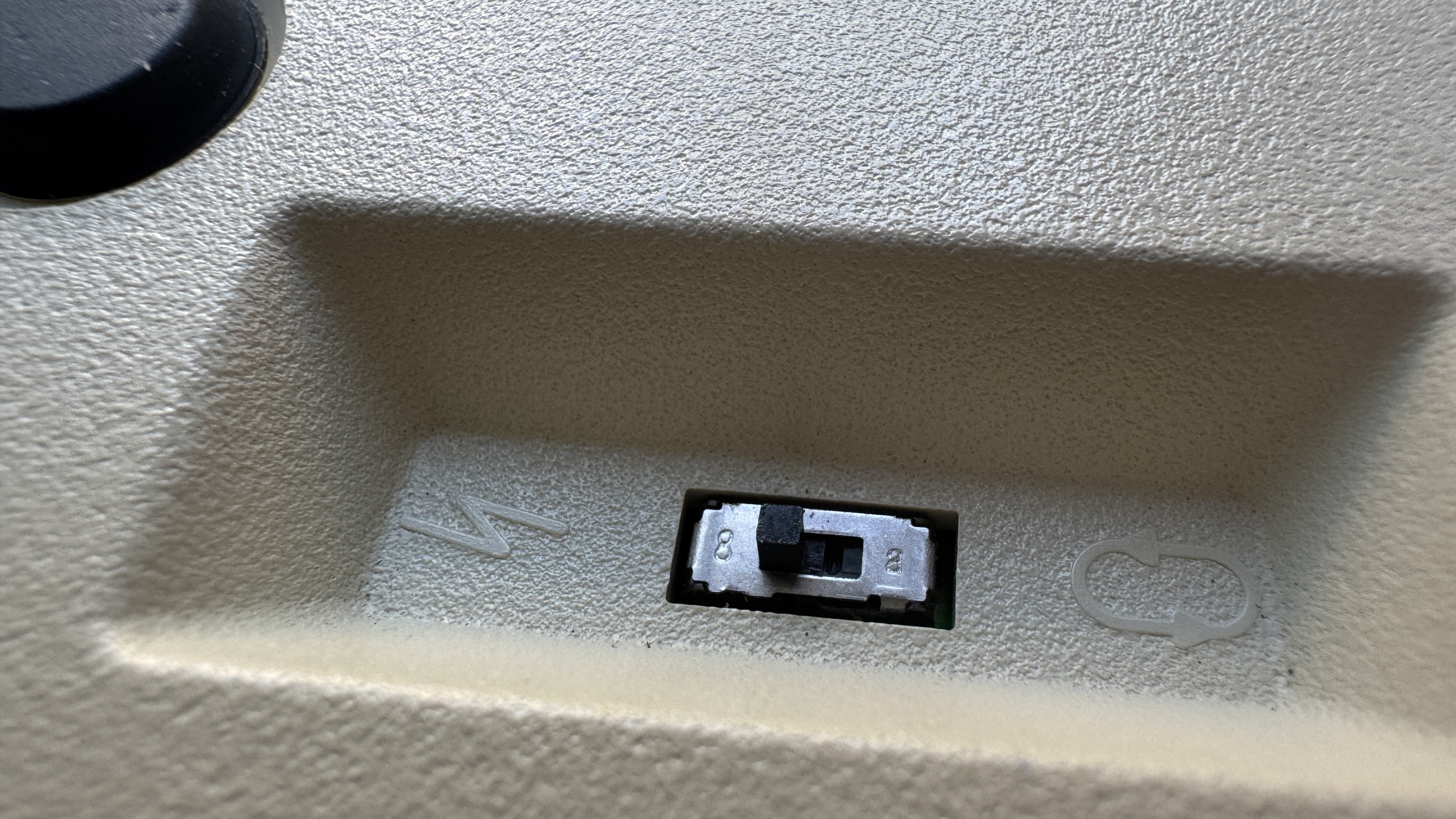
The LPFK I used has a two-position slide switch:
Left — behaves like diagnostic/attention: it will accept bytes from the host, and without proper init you’ll see the classic “all LEDs flash → off” acknowledgement.
Right — local echo mode: pressing a key lights that key locally; serial commands are ignored and no keycodes are sent.
For host control, set it to ⚡, then do the reset + enable sequence (below).
Serial testing
Port (macOS): /dev/tty.usbserial-…
Settings: 9600 baud, 8 data bits, odd parity, 1 stop (8-O-1), no flow control.
Tooling: picocom 3.1+ works well:
picocom --send-cmd "cat" -b 9600 -d 8 -p o --raise-dtr --raise-rts /dev/tty.usbserial-XXXXXXReady-to-send test files (macOS):
# reset / enable / disable
printf '\x01' > ~/LPFK/reset.bin
printf '\x08' > ~/LPFK/enable.bin
printf '\x09' > ~/LPFK/disable.bin

# clear and all-on
printf '\x94\x00\x00\x00\x00' > ~/LPFK/all_off.bin
printf '\x94\xff\xff\xff\xff' > ~/LPFK/all_on.bin

# single-key examples (light only 0x0A and 0x1F)
printf '\x94\x00\x20\x00\x00' > ~/LPFK/only_0a.bin   # 0x0A
printf '\x94\x00\x00\x00\x01' > ~/LPFK/only_1f.bin   # 0x1F
Picocom usage:
Ctrl-A S  ~/LPFK/reset.bin
Ctrl-A S  ~/LPFK/enable.bin
Ctrl-A S ~/LPFK/only_0a.binHeads-up: The device typically sends
0x81after a valid0x94bitmap (ACK). If you see0x80, retransmit the bitmap.
Necessary boot ritual: After opening the port in ⚡ mode, you must send Reset (
01) then Enable (08). Before0x08you’ll only see the “flash once” ack behavior; after0x08, keycodes start flowing.
To see non-printable keycodes as hex: add
--imap 8bithex,lfhex,crhex,tabhex,spchexto picocom.
The protocol that finally worked
Once the wiring+serial were right, the remaining barrier was mode and command bytes. After many attempts, I finally got the protocol right. The LPFK uses a simple byte protocol (no SOH frames needed):
Host → LPFK
0x01= Reset (leaves device disabled, LEDs off)0x06= Read Configuration (LPFK replies0x03)0x08= Enable (enter reporting/controllable mode)0x09= Disable0x94 <b0> <b1> <b2> <b3>= Set Indicators (LED bitmap)
LPFK → Host
0x00..0x1F= Key press (32 keys)0x80= Retransmit (LED bitmap parse error)0x81= OK (LED bitmap accepted)
Reading keys and lighting LEDs
Keycodes: Each press emits one byte 0x00..0x1F. These are ASCII control chars; a dumb terminal turns some into newlines. Render as hex to see them clearly.
LED bitmap (0x94 b0 b1 b2 b3): The four data bytes are little-endian groups, each group controls 8 keys:
b0→ keys00..07b1→ keys08..0Fb2→ keys10..17b3→ keys18..1F
Within each byte, bit7 lights the leftmost key of that 8-key block; bit0 lights the rightmost. (This matches published notes and our tests.) brutman.com
Physical geometry vs. scan order: My unit has a 6-row faceplate (4 + 6 + 6 + 6 + 6 + 4), but the scan is linear left→right by rows:
LPFK Serial Demo
0x
IBM LPFK
A basic driver
I wrote a basic Node.js driver for the LPFK.
gist.github.com/ecrecover/lpfk.js
This minimal script will:
- (a) open the port
- (b) reset+enable
- (c) print keycodes as hex
- (d) light LEDs
- (e) run a simple animation
And here's a demo:
References
- Protocol, wiring & power for 6094-020 (serial variant) — Michael Brutman’s excellent write-up with pinouts and command bytes. brutman.com
- Ardent Tool — background on 6094 LPFK variants (RS-232, TTL, Japanese models; power supplies; attach kits). Ardent Tool of Capitalism
- IBM docs (field FRUs) — LPFK 6094-020 and serial/power cable part numbers show up in Power/RS/6000 service tables. IBM Public Cloud
- High-level description — LPFK as an IBM context-sensitive input device for CAD/graphics. Wikipedia